Of antennas as used by administrations for HF broadcasting and other services. For the first time in a CCIR Recommendation the computer programs are an integral part of the.
3 1 Schematic Diagram Of Log Periodic Dipole Antenna Download Scientific Diagram
In this article we will however focus mainly on the LPDA is its classic configuration along with several other offshoot derivatives.

. Our LPH-1 Military Type AS-3520F features a rotatable log periodic array RLPA that is lightweight high strength corrosion resistant and has a rotary joint that allows for continuous. The log periodic antenna is a specialized antenna with unique advantages. Enrique Ayala shown in Figure 3.
Designed and produced to give top performance and reliable. We will go through the design of a real world Log Periodic Dipole Antenna which was done by a Mr. 21-Element Very High FrequencyUltra High Frequency Log Period Dipole Array.
Based on the physical characteristics of vertically polarized waves maximum sensitivity is possible at low and medium elevation angles and the RSHL210A3 radiation pattern is ideal for this. As ψ is increased from 0 to 50 the impedance increases to approximately 160 ohms. The north antenna is used with various receivers for detection of meteor trail.
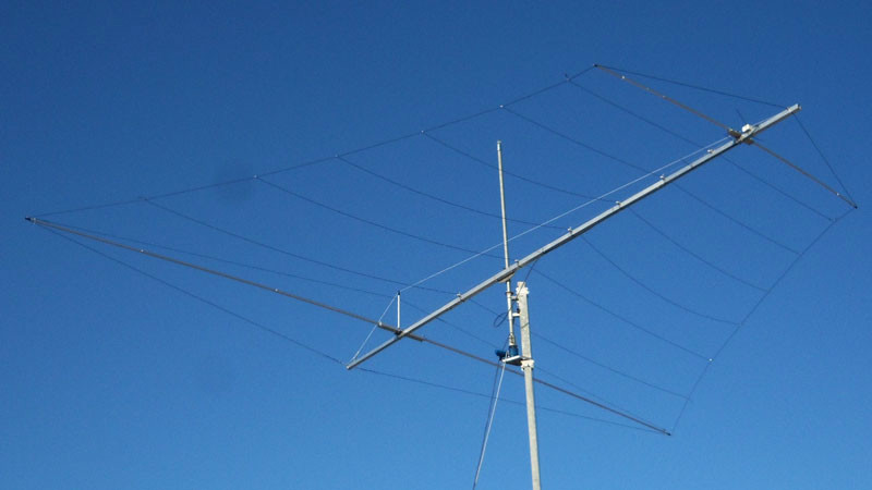
The log periodic looks much like a multi-element Yagi antenna in that it has parallel elements mounted along a. I used a spreadsheet template from Dave Leeson W6NLs Yagi design book 4 which calculates the conversions. Photo courtesy of Frank K7SFM.
AT VLP-2-28 AT VLP-27-28 and AT VLP-4-28. Arrays of half-wave horizontal dipoles. The design is broken down as shown in Figure 4.
Since most HF antennas require elements of tapering size a conversion method is required. A good impedance match VSWR. Spacing between the feeders booms is generally set to give an impedance in the order of 100 ohms.
The design simulation and experimental investigation of a triple-band Log-Periodic Dipole Antenna is presented. The RSHL210A3 log-periodic HF antenna can receive ground waves and vertically polarized skywaves and detects very weak signals. From the design frequency of the array.
The LPDA is used extensively for HF VHF and UHF radio communications. With up 20kW average power low take-off angle and up to 18dbi directional gain it is perfect for medium to long. And what is left for you to do is easy to assemble.
Reception is possible from 2 MHz allowing all distances to be covered. Lets take a quick look at the general construction of a log periodic and then consider the question response options. A log periodic antenna for the HF bands.
The design concentrates radiation vertically at the higher overhead radiation angles making it suitable for short range NVIS HF communications 0-300kms and for medium range transmissions. ACOM Bulgaria manufactures a range of 8 10 and 12 element HF log-periodic antennas. Measured and calculated antenna gain CONCLUSIONS The design measurement and analysis of radiation patterns gain and VSWR of a 1690 MHz 2200 MHz log-periodic dipole antenna has been presented.
A thorough comprehensive guide to the design building and use of High Performance Log Periodic Antennas. Their main features are. The LPH-89 Military Type AS-3482GRC allows high power communications between fixed and mobile stations such as ships aircraft or tactical deployments.
We will use a total of N25 elements dipole antennas with diameters of 0077. Most of the antennas described by Bill cover a frequency range of 14 to 30 MHz. The south antenna is dedicated to the e-CALLISTO solar spectrometer described here.
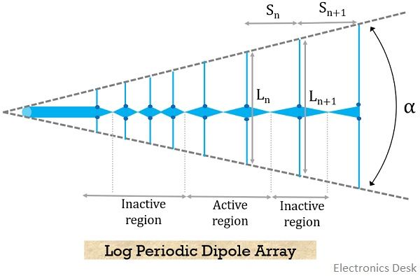
Quadrant antennas and horizontal dipoles. In the whole band the measured antenna gain exceeds the target value of 87 dBi and VSWR is below the desired limit of 15. The concept of the Log-Periodic array was initially conceived in the year 1958 by two researchers at the University of Illinois in the USA.
The compact rotatable RSHL451 log-periodic HF antenna can be used to transmit and receive horizontally polarized waves. Our HF Broadband Vertical Log Periodics are almost 100 efficient and are short to medium range antennas. Rhombic antennas and vertical monopoles.
The expansion factor k is 11 as shown. NEC-2 antenna design software uses a single wire of a constant diameter for each element to calculate antenna characteristics. The antenna transmission frequency range from 5 MHz to 30 MHz makes it particularly suitable for communications over medium and long distances.
Our horizontal log periodic antennas are designed specifically for targeted communications. All elements are riveted no corrosion-vulnerable clamped joins. For log-periodic dipole arrays the impedance values range from about 60 to 100 ohms.
Enrique holding his LPDA Antenna. Lencom makes both horizontal and vertical log periodic antennas to suit large-scale communication or radar requirements. And because the antenna designs discussed earlier are based upon resonant elements off-resonance operation introduces reactance which causes the SWR in the feeder system to increase.
LS86 Assembling Manual LS86. As may be seen in Fig1 the log-periodic array consists of several dipole elements which each are of different lengths. We have two Creative Design CLP5130-1N log periodic antennas in service one north and one south.
These antennas are for the serious antenna enthusiast who has access to a tower and a supply of aircraft certified aluminum or titanium.
What Is Log Periodic Antenna Working Characteristics Advantages Disadvantages And Applications Of Log Periodic Antenna Electronics Desk
14 28 Mhz Log Periodic Antenna

Hf Antenna Multiband Antenna Logperiodic Antenna Log Periodic Antenna Prosistel Pro Sis Tel

R S Hl451 Log Periodic Hf Antenna
1 A Simple Log Periodic Antenna Log Periodic Dipole Antenna Download Scientific Diagram

3 Element Hf Yagi For 21 And 28mhz
Hf Antenna Multiband Antenna Logperiodic Antenna Log Periodic Antenna Prosistel Pro Sis Tel

Hf Log Periodic Antenna Lp 1005aa 3 0 30 0 Mhz
0 comments
Post a Comment